xMASS SDR
A modular, high-performance 8×8 MIMO transceiver optimized for 4G/5G application, research, beamforming, direction finding and wideband spectrum monitoring. The xMASS provides eight synchronized RX and eight synchronized TX channels with flexible clocking, calibration and host I/O for coherent multi-channel acquisition and transmission. Its modular design allows for easy maintenance and enables the construction of high-order MIMO systems using the same building blocks.
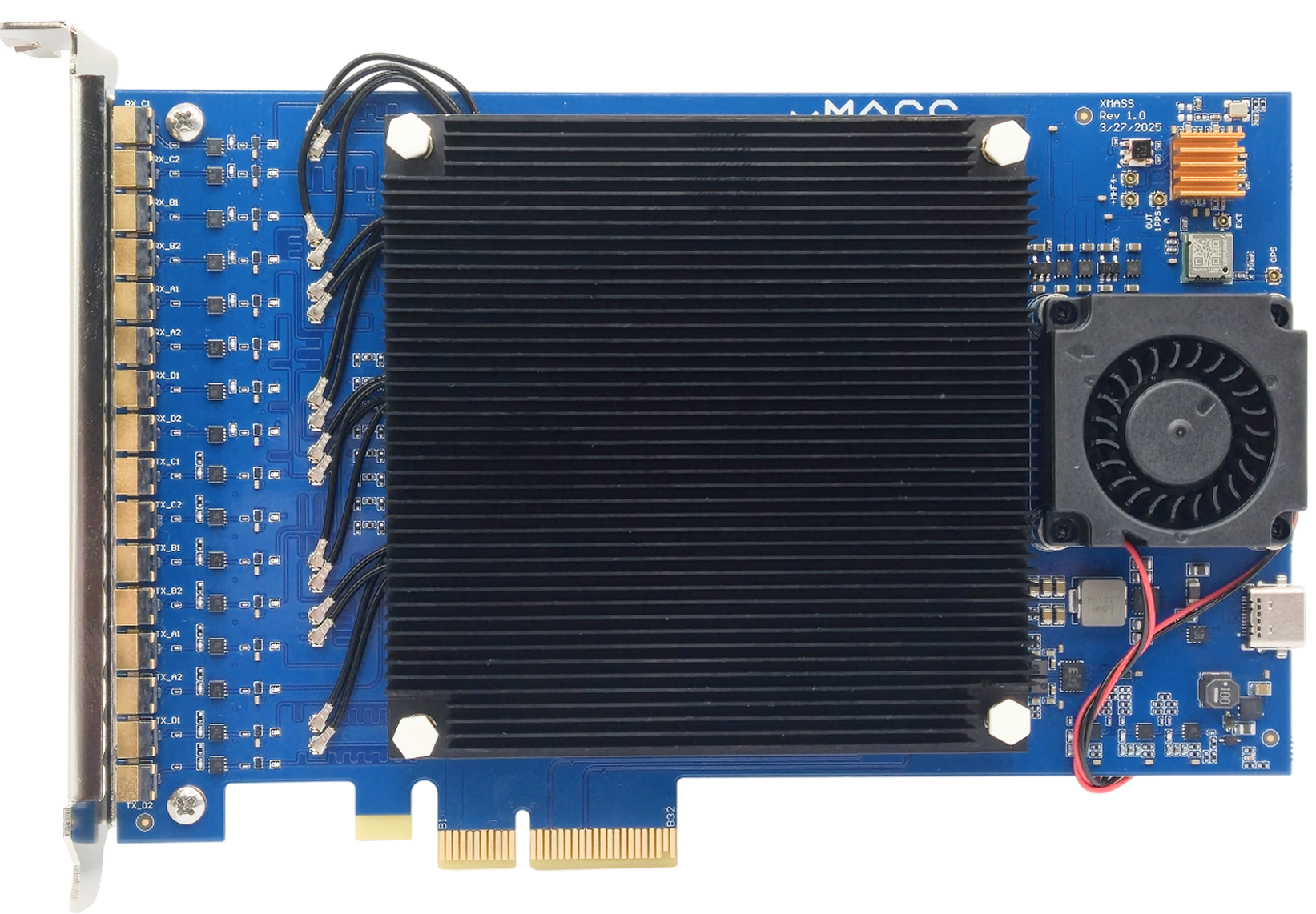
Overview

General Specifications
- FPGA
4× AMD XC7A35T
- Clock Synchronization
LMK05318
- Module Host Interface
PCIe 3.0 x2 connection
- Form Factor
PCIe x4 (2 PCIe lanes used)
- Power Consumption
20W Typical
- Extended Power Supply Range
2.85 - 5.5 V
RF Specifications
- RFIC
4× LMS7002
- Frequency Range
30 MHz to 3.8 GHz
- Sample Rate
0.1 MSps - 100 MSps
- Channel Bandwidth
0.5 MHz - 90 MHz
Target Applications
- Spectrum Monitoring
4× M.2 2230 Key A+E xSDR for comprehensive frequency analysis and monitoring
- Cellular Communication
Enables next-generation 4G/5G wireless networks with high-order massive MIMO
Fully compatible with Amarisoft and srsRAN
- Directional Finding
Determines the direction of arrival (DoA) of incoming radio signals, enabling precise localization of transmitters
- Beamforming
Focuses signal transmission and reception in specific directions
Enhances range, improves signal quality, and reduces interference in multi-user environments
Bifurcation Modes
The xMASS supports configurable bifurcation modes that partition the physical 8 RX / 8 TX channel array into one or more independent logical streams. Bifurcation determines how RF channels, FPGA resources, and host I/O are grouped and advertised to the host. Selecting a bifurcation mode affects aggregate throughput, per-device sample-rate limits, synchronization behaviour, calibration routing, and the available MIMO processing scope.
Available bifurcation modes are:
Full 8×8 MIMO
All 8 RX and 8 TX channels are presented as a single logical device with full cross-channel synchronization and shared calibration paths. This mode enables true 8×8 spatial processing (beamforming, full-array DoA, high-order MIMO benchmarks).
When to use: research/measurement requiring maximum antenna aperture, advanced beamforming or direction-finding, or when coherent processing across all channels is required.
2 independent 4×4 MIMO systems
The 8×8 array is split into two independent 4×4 logical devices. Each group has its own stream context and can be controlled separately while still retaining 4×4 MIMO capability within the group.
When to use: deploying two separate 4×4 systems (for example, two co-located base stations or one monitoring system plus one comms system), or when slightly reduced MIMO order still meets spatial processing requirements but host/throughput constraints dictate partitioning.
4 independent 2×2 MIMO systems
The array is split into four independent 2×2 logical devices, each suitable for small-scale MIMO links or parallel monitoring tasks.
When to use: scenarios requiring multiple independent narrow-band links or many small testbeds.
Connections
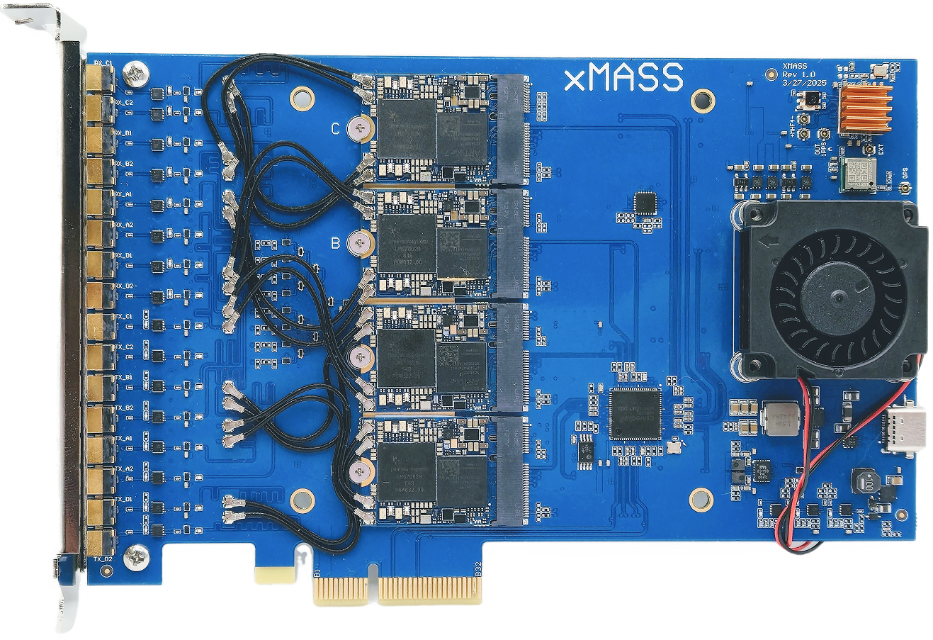
Front side
Note
The xMASS SDR has 4 slots for M.2 xSDR modules. Slot A is the master module and is required for the xMASS to control the AF part of the board.
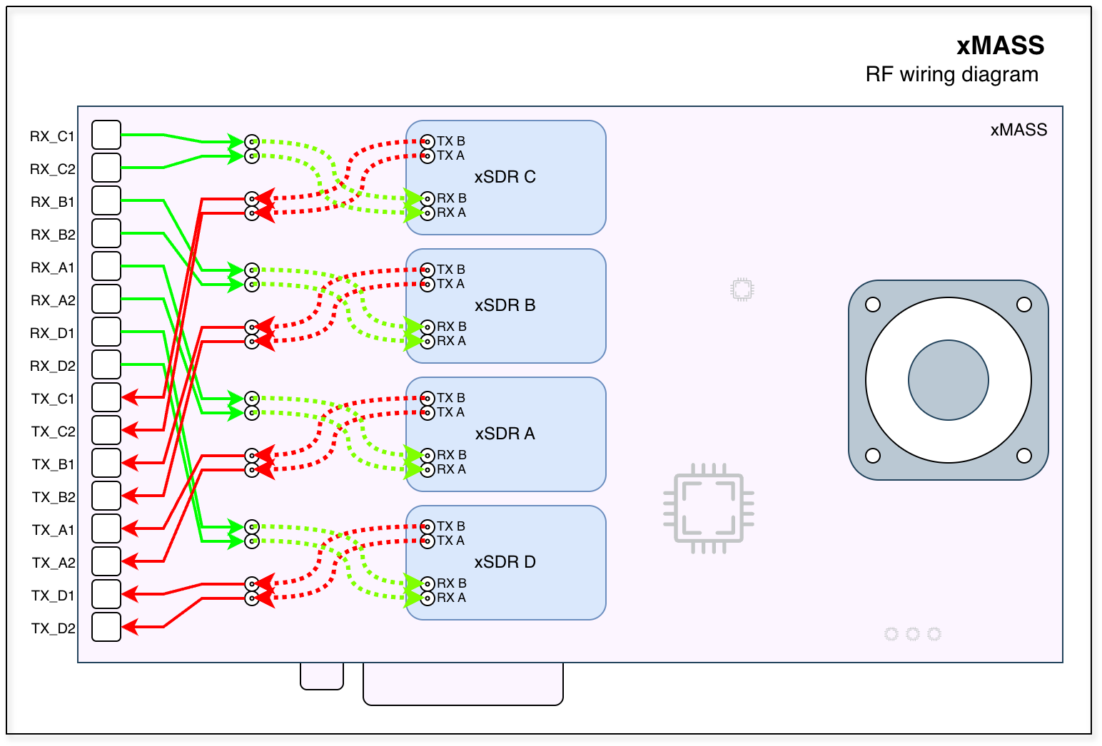
The MHF4 connector of each xSDR module should be connected as shown in the picture above. Please note that the cables should be connected crosswise.
Back side
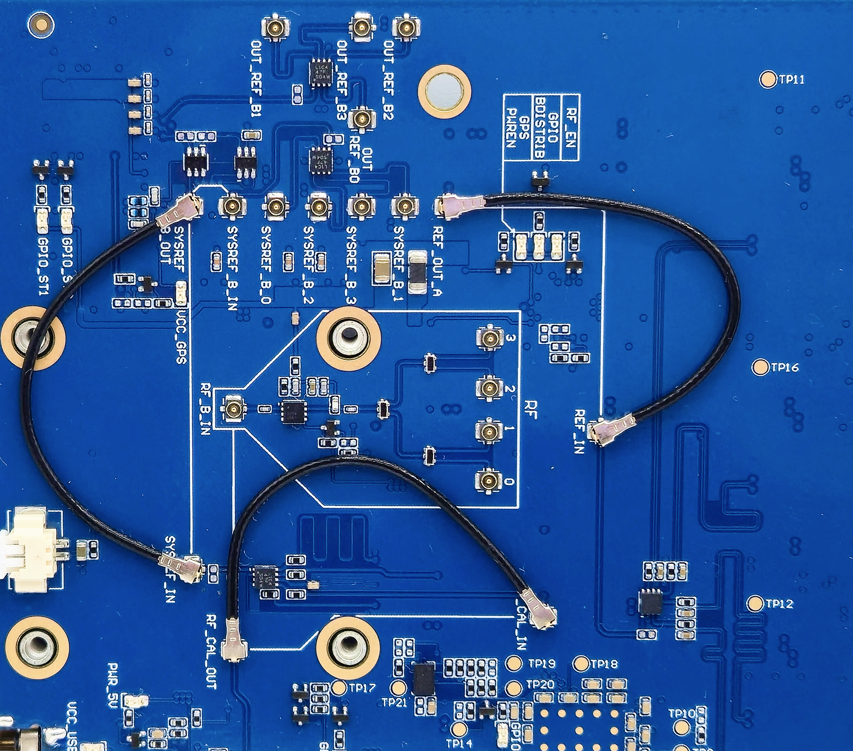
The back side of the xMASS SDR contains the clocking and synchronization circuitry, RF distribution network and calibration sources. The picture below shows the standard standalone configuration with one xMASS SDR board.
PCI bracket panel
The bracket panel of the xMASS SDR has 16 external MMCX connectors for RF signals. The top 8 connectors are RX channels, and the bottom 8 connectors are TX channels.
Clocks and synchronization
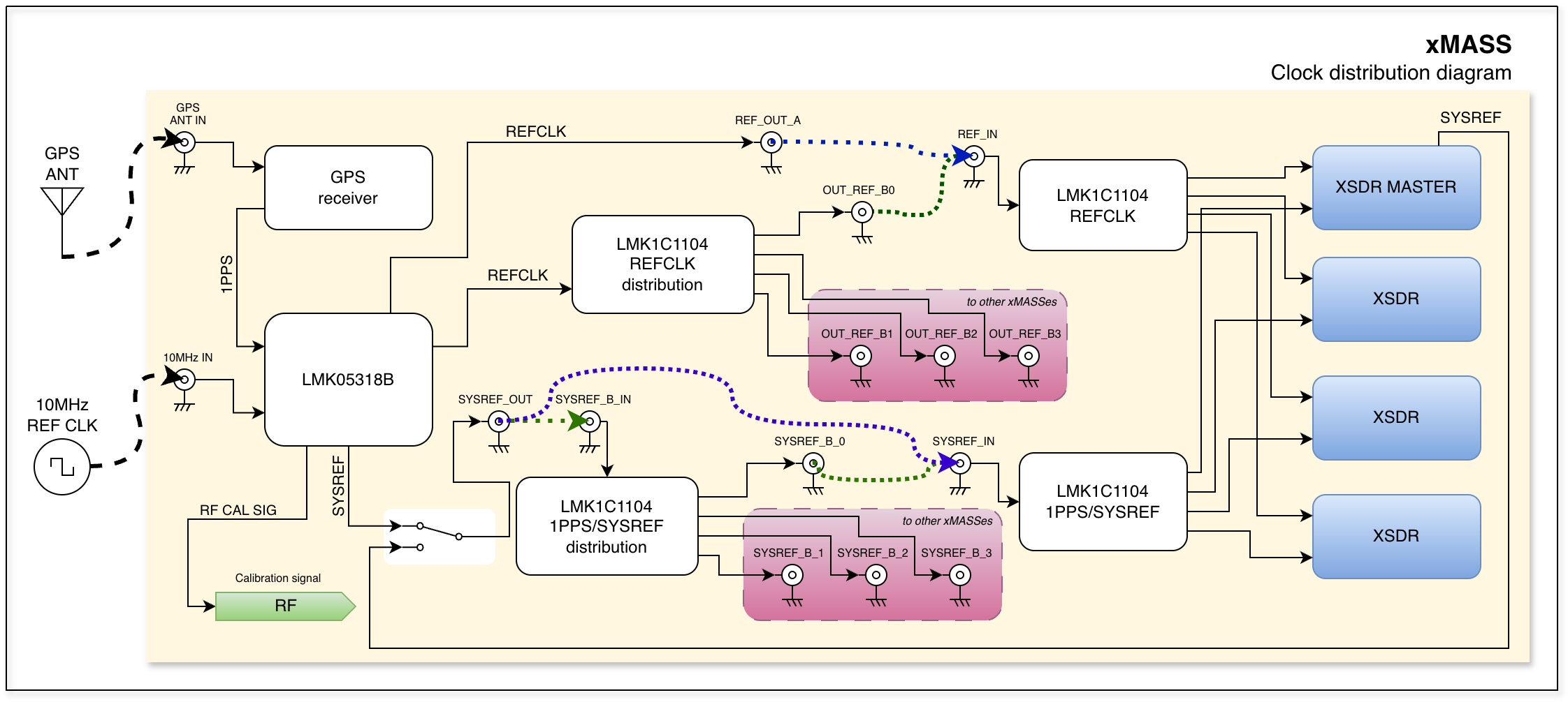
There are two clock domains on the xMASS SDR:
REFCLK: The continuous reference frequency distributed to the xMASS board and all attached xSDR modules.
SYSREF: A timing/event synchronization pulse distributed to all xSDR modules.
The LMK05318B serves as the central clocking IC on the xMASS SDR and can use different clock sources:
On-board crystal oscillator.
External reference clock input (10 MHz typical; range: 10 MHz to 40 MHz).
GPS synchronization using the on-board GPS module.
The IC produces the following output signals:
Reference clock output to all xSDR modules.
SYSREF output to all xSDR modules.
Calibrated reference clock output for the RF calibration loop.
Note
Standalone mode
The standalone mode provides a self-contained clock and event synchronization scheme for a single xMASS board.
Signal flow
Physical connections:
REF_OUT_A->REF_IN(local reference routing to module A).
SYSREF_OUT->SYSREF_IN(local SYSREF distribution).
Logical behaviour:
LMK05318B drives local REFCLK and SYSREF to all onboard xSDR modules.
An optionally-attached external source or GPS may be selected as the REFCLK input.
Multiboard mode
The multiboard mode provides a distributed clock and event synchronization architecture for multiple xMASS boards so that REFCLK and SYSREF are common and phase-aligned across the whole array.
Signal flow (master / slave)
Master board:
OUT_REF_B0->REF_INon master (primary reference distribution output).
SYSREF_OUT->SYSREF_B_INon master (SYSREF distribution input/output routing).Slave boards:
OUT_REF_B1,OUT_REF_B2,OUT_REF_B3->REF_INon each slave board as required.
SYSREF_B_1,SYSREF_B_2,SYSREF_B_3->SYSREF_INon each slave board respectively.
Logical behaviour
One board acts as the master reference source; other boards lock to that source for both REFCLK and SYSREF.
LMK05318B on the master can be driven by GPS or an external disciplined source to provide absolute time/frequency across the entire array.
RF distribution

Note
Standalone mode
The standalone mode provides a closed-loop calibration path and a local RF calibration reference when a single xMASS board is used.
Signal flow
RF_CAL_OUT->RF_CAL_IN(local calibration loop through the frontend on the same board).Calibration source (
NOISEorCAL) is switched into LNA/RX paths under software control when required.
Multiboard mode
The multiboard mode provides calibration and routing scheme for multiple synchronized xMASS boards so that calibration signals and RF paths are common across the array, enabling coherent multi-board MIMO and consistent calibration measurements.
Signal flow (master / slave)
Master board:
RF_CAL_OUT->RF_B_IN(feeds the distributed calibration bus that other boards listen to).
RF_0->RF_CAL_IN(local calibration loop using the master board’s RF path).Slave boards:
RF_1,RF_2,RF_3->RF_CAL_INon each additional (slave) board, respectively (receive the calibration reference from the master).
Note
Calibration network
The board includes a NOISE source that can be used for calibration and testing. In addition, the LMK05318B can provide a calibrated reference signal for the RF calibration loop.
Calibration signals can be routed to each channel using series software-controlled switches.
The possible RF paths are:
Normal RX/TX path: TX from MMCX to xSDR module and RX from xSDR module to MMCX.
Calibration path: NOISE or CAL signal to xSDR module for RX calibration.
Loopback path: TX from xSDR module to RX of the same channel for loopback testing.
In addition, the NOISE/CAL signal can be routed to the first channel(LNAL_A) of each xSDR module directly through the M.2 socket.
This avoids using the RF frontend, resulting in more accurate calibration.
Frontend control
Note
usdr_registers tool.GENERAL
This section describes the general control of the board.
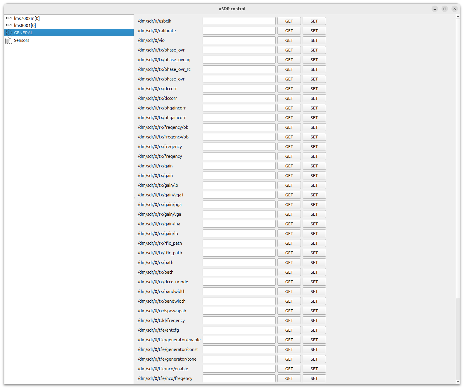
/dm/sdr/refclk/path- Reference clock source selectionOptions:
internal - Internal clock source/Single board operation
external - External clock source/Multi board operation
/dm/sdr/refclk/frequency- Reference clock frequency in Hz
/dm/sdr/0/sync/cal/path- Calibration path selectionOptions:
0 - Normal operation
1 - LO
2 - NOISE
3 - LO_LNA3
4 - NOISE_LNA3
/dm/sdr/0/sync/cal/freq- LO calibration frequency in Hz
xmass_ctrl
This section describes the low level control of the board.
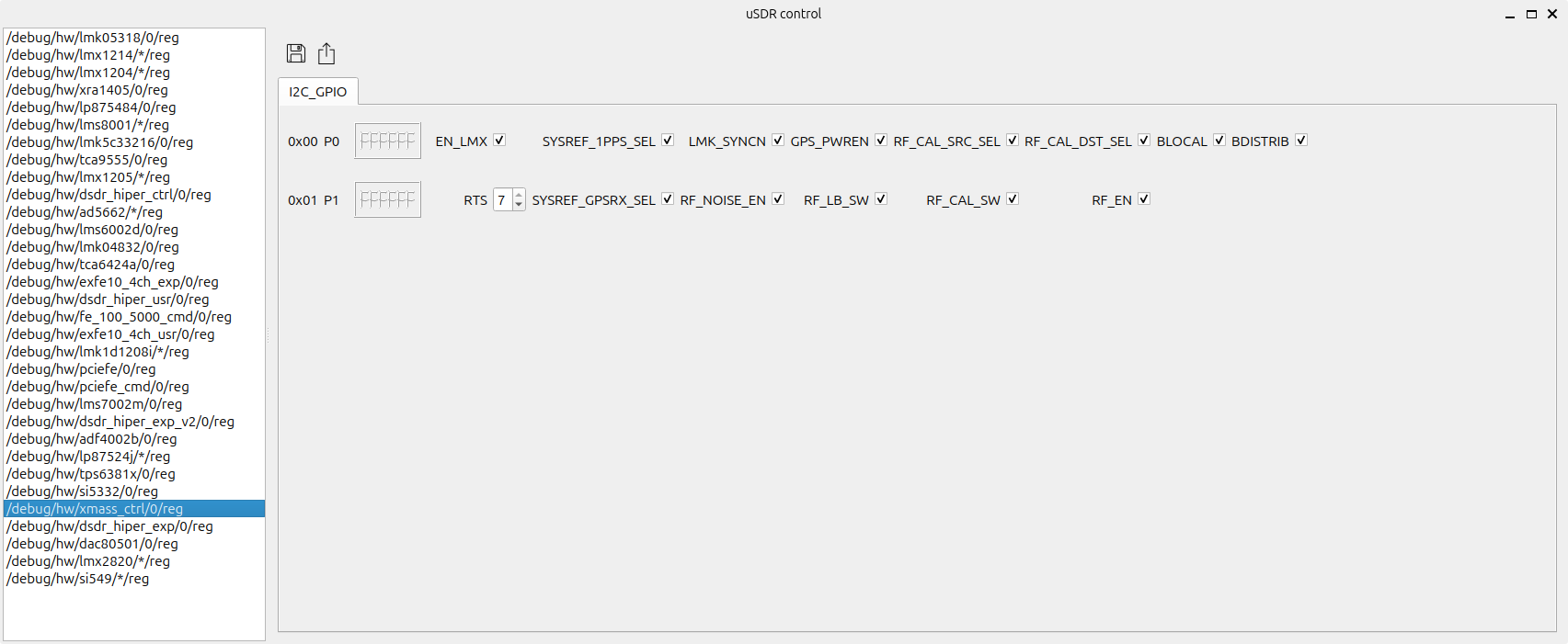
Register |
Field |
Description |
|---|---|---|
P0 |
BDISTRIB |
Enable OUT_REF_B and OUT_SYSREF_B for 4 sync boards |
P0 |
BLOCAL |
Enable local PPS and REF distribution |
P0 |
RF_CAL_DST_SEL |
0 - RF_CAL_EXT (general RX port) / 1 - RF_CAL_INT (LNA3 port) |
P0 |
RF_CAL_SRC_SEL |
0 - RF_LO_SRC (from LMK) / 1 - RF_NOISE_SRC (from NOISE GEN) |
P0 |
GPS_PWREN |
Enable GPS module and DC-bias |
P0 |
LMK_SYNCN |
Set LMK05318B SYNC_N port |
P0 |
SYSREF_1PPS_SEL |
0 - LMK_1PPS / 1 - From SDR_A |
P0 |
EN_LMX |
Enable LMK05318B |
P1 |
RF_EN |
Enables Power Amplifiers |
P1 |
RF_CAL_SW |
0 - Use RF cal source as FB / 1 - Use XSDR TX as FB |
P1 |
RF_LB_SW |
0 - Normal operation / 1 - use loopback path to XSDR RX |
P1 |
RF_NOISE_EN |
Enable 14V generator for Zener noise source |
P1 |
SYSREF_GPSRX_SEL |
0 - TX_SYREF_MUX demultiplexing to CLK_SYSREF_OUT / 1 - TX_SYREF_MUX to GPS_RX |
P1 |
RTS |
Interboard sync logic(Not used) |
Software
Note
Note
SYSREF
In order to select synchronization mode, you have to pass one of the following values to the usdr_dms_sync api call.
The usdr_dm_create utility also supports the same options for the -s command line argument.
all- enable all supported sync sources (sysref, stream-based, external PPS, etc.).1ppsorsysref- explicit sysref via an external 1PPS pulse (external PPS/sysref).sysref+gen- explicit sysref via internal source (using onboard LMK05318B).rx- use the RX stream as the synchronization source.tx- use the TX stream as the synchronization source.any- accept any available sync source (choose the best/first available).none- disable synchronization (no automatic sync).off- turn sync off / explicitly stop syncing (used in code before starting streams).
Examples
In order to use xMASS SDR, you can use the usdr_dm_create utility to receive or transmit data. The following example creates a raw IQ data file with a sample rate of 10 MSamples per second per channel, a center frequency of 1700 MHz, using all 8 RX channels:
usdr_dm_create -D bus=pci/dev/usdr0:/dev/usdr1:/dev/usdr2:/dev/usdr3 -r10e6 -l3 -e1700e6 -c -f output.raw
If you want to enable synchronization using SYSREF, you can add the -s sysref option to the command line:
usdr_dm_create -D bus=pci/dev/usdr0:/dev/usdr1:/dev/usdr2:/dev/usdr3 -s sysref -r10e6 -l3 -e1700e6 -c -f output.raw
The first device in the list(usdr0 in this example) should be the master xMASS SDR board(slot A).
The software stack supports the SoapySDR interface, so you can use any compatible application.